
5G Private Network and Innovative Applications Realize Smart Living

Author(s)
Hung-Yin TsaiBiography
Dr. Tsai is currently a distinguished professor of the Department of Power Mechanical Engineering, National Tsing Hua University (NTHU). He joined National Tsing Hua University in 2008. He has been the department chairman, associate vice president for academic affairs, and dean of the School of Continuing Studies.
Academy/University/Organization
National Tsing Hua University-
TAGS
-
Share this article
You are free to share this article under the Attribution 4.0 International license
- ENGINEERING & TECHNOLOGIES
- Text & Image
- August 17,2021
A system of image positioning and decoding is proposed. The techniques used in the system include image processing, machine vision, and machine learning. With the appropriate image capture system and pattern design and manufacturing, the moving target can be positioned on the micrometer scale. The "positioning" of the image positioning and decoding system means the procedure of detecting the special pattern and finding image coordinates of the center of the special pattern. "Decoding" is similar to the QR code concept. Through the positioning and decoding steps, we can acquire the absolute coordinates of the special pattern and link the image coordinates and absolute coordinates together, giving a pixel in the image a corresponding actual location in reality. In addition to having functions like optical scale and magnetic scale which can be used to measure the movement of mechanical parts, the image system has the advantage of integrating other image processing technologies. Therefore, an algorithm to measure the length of objects can be built based on this image system.
Because of the tolerance of workpieces when manufacturing, the sizes of workpieces can differ from those in CAD files. On the other hand, the workpiece usually needs the fixtures to fix and position its location while manufacturing. However, under micron-level processing conditions, the manufacturing tolerances of general fixtures have already exceeded this accuracy, so the picking and placing positions of the workpieces will deviate from expectations. Because the actual coordinate position of the workpiece deviates due to the pick-and-place object, it will affect the performance of the machining accuracy.
The general image measurement method is to measure on a single image. In order to see the complete object in a single field of view, the camera's magnification should be small, and the measurement accuracy will decrease accordingly. However, if a high-magnification lens is selected for measurement accuracy, usually the camera field of view can only see a corner of the object. In order to measure objects beyond the field of view, the positioning information of the X-Y table is usually relied on. Generally, the positioning of the X-Y table relies on an optical scale or a magnetic scale. The method used in this study is different from the two. The X-Y table is positioned through image positioning, and a 4.5-magnification lens is used to improve the image positioning accuracy. Machine vision technology extracts the feature points of the object to be measured for size as shown in Figure 1.
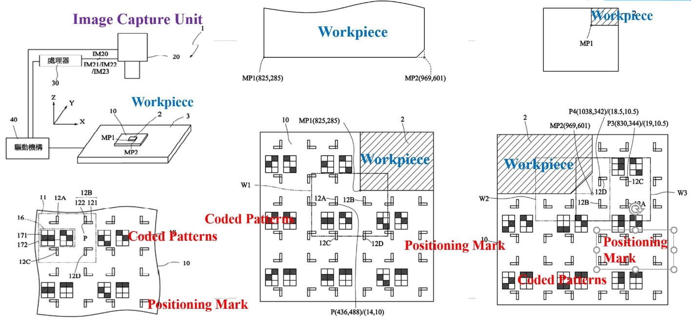
Figure 1. Schematic of positioning and measuring system
The algorithm flowchart is shown in the Figure 2 below, and is divided into four parts: (1) Object edge detection: Since the edge of the object has obvious and continuous pixel intensity tomography, the directional gradient histogram is used as the feature. Then a moving window is used to scan the entire image step by step; the image feature information captured by the window is transferred into a pre-trained support vector machine for interpretation; the positions of the horizontal and vertical edges are detected and recorded; (2) Terminal point detection: The horizontal and vertical edge images obtained by object edge detection are converted to Hough line segment conversion, and the intersection of the two lines is recorded to obtain the end point of the line segment; (3) Positioning mark detection: Since the coded patterns on the image scale are generally not perfect and are slightly different from the original design, first shadow removal and median filtering are used to get a clean and suitable image, and then the geometry of the positioning mark characteristics is used for detection; (4) Decoding: The relative position of the coded patterns used for decoding and the positioning mark is fixed, so when the positioning mark is detected, the pixel value at the relative position can be calculated. Moreover, the decoding action can be carried out to obtain the image scale coordinates of the positioning mark.
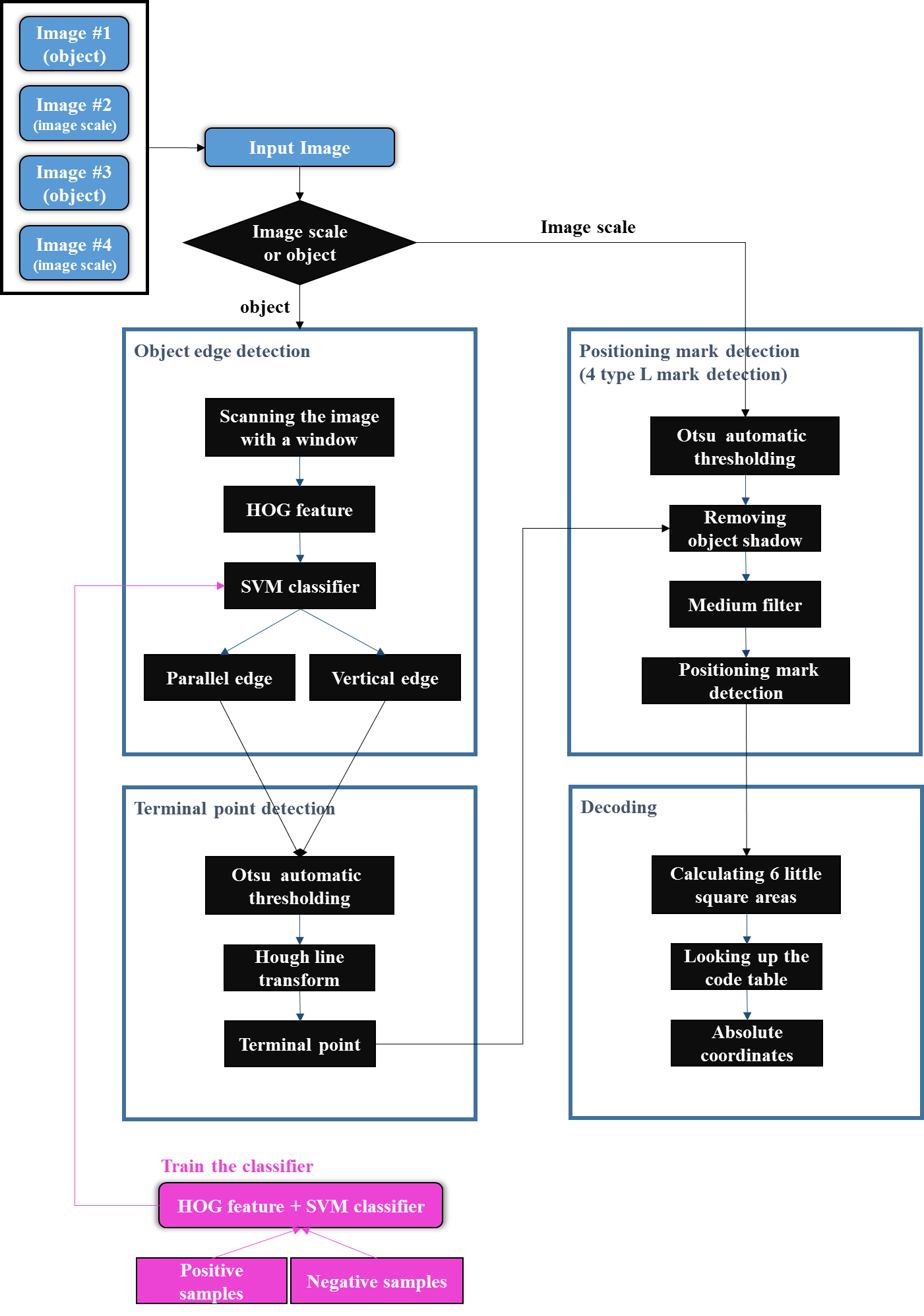
Figure 2. Algorithm flowchart
In order to solve the limitation that the measured object size must be smaller than the camera's field of view when measuring objects with pure images, this research proposes the concept of image scale based on placing the object to be measured on a carrier with positioning marks and coded patterns. The object and the patterns are photographed at the same time using the camera, and the actual position of the partial appearance of the object in the image is recognized by analyzing the pattern (Figure 3). In this way, as long as the object to be shot is placed on the image scale, the measured object is no longer limited by the field of view of the camera, and does not need to rely on the positioning accuracy of the platform; the length can thus be measured. Taking a 4 mm gauge as an example in the study, the average measurement length is 4011 µm, and the average error is 11 µm.
In addition to measuring the length of the object, the image scale can also be used alone as the positioning basis when the object is moving. For example, by obtaining the pixel coordinates in the "L" symbol image and the coordinates of the "L" symbol on the image scale, the relative moving distance between the image scale and the camera can be calculated as the positioning function of an optical scale or a magnetic scale. The repeatability can be in ± 2 pixels based on the optimization of the parameters of the Hough line segment conversion.
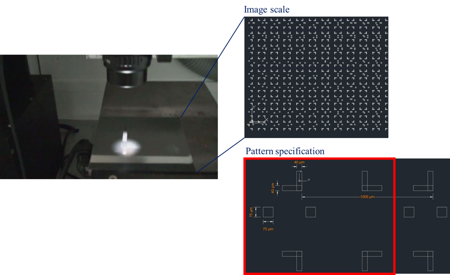
Figure 3. Actual object and designed patterns
RELATED

STAY CONNECTED. SUBSCRIBE TO OUR NEWSLETTER.
Add your information below to receive daily updates.